This page designed to operate under
Netscape Navigator(TM) Version 2.0
Last update 02JUN2019
CMM1000
Motor brushes (part # 429892-00) are no longer
available. I successfully replaced mine with 2 each part number 2221764 from Eurton Electric Company, Inc . At
$8.20 each, well worth it for the return of motor power. You have to grind off
about a quarter inch of the length to get it to fit, but that's an easy task.
Cut off the braid to each original brush save for about an inch and crimp the
new brush spade connector there.
HW-101
Low voltage at V13 pin 7: I was only getting 70 volts or so here. R231 (220K) and R316 (22K) at V14 were way out of tolerance.
S-meter reading backwards: In my case, there was a break in the brown wire going to the board from meter switch lug 5 inadvertently grounding the positive side of the meter. This led me to the next note…
Schematic Error: There are two connection nodes labeled "To Meter SW-5" and "To Meter SW-1" connected to either side of R115. These are reversed.
S-meter not reading, but rises with RF Gain turned down: Go thru the tune-up procedure for T201, T102 and T103. I recommend the following:
1. Monitor the audio with a scope at the product detector V13 pin7. There you can get visual as well as audio feedback when you adjust to the sine wave from the calibrator. You need to be off the cal signal a bit to get a, say, 1kHz tone to work with. Peak the audio by tuning T201 per the Heath instructions but watch as well as listen.
2. For the other two transformers, T102 and T103, Heath suggests that these come from the factory close to the proper setting. May be, but with a 40-year-old boat anchor there’s no telling where they are now. I screwed around with these two for some time and got all kinds of oscillations near peak points. I have heard others complain of such symptoms and I wonder if this is their problem area. Try this method: Monitor the voltage at V13 pin 1 (the cathode of D101 is easy to grab) and shoot for about -0.9V as you tune. I seem to recall starting the lugs at the top and bottom and winding them toward the center looking for the voltage to rise from several volts negative and peak just shy of zero. Do T102 then T103 and repeat.
3. Turn off the calibrator and make sure the antenna is disconnected. Zero the meter using the control on the chassis side.
(KR4ZB)
HW-101, SB-101 Heterodyne Crystal Bank Replacement with DDS
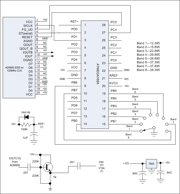
This has been a long term project I went back to. These old crystals lose their activity and are nearly impossible to find. I built my home-brew transmitter based on the Chinese AD9850 synthesizers available for a few dollars and used the ATMEGA168 to control it. Along the line I had purchased some spare boards to replace some of my troubled ones and used a wafer switch from one to indicate the desired frequency to the microcontroller. Here's the schematic I came up with.

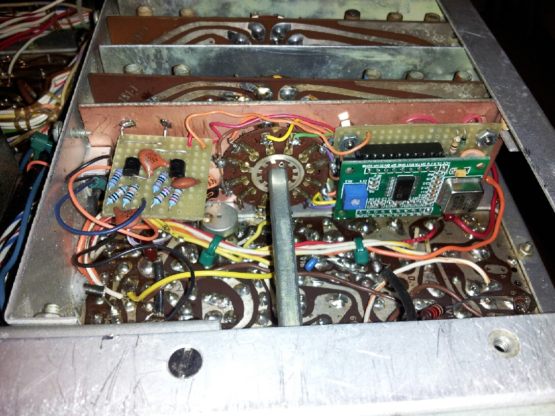
The output buffering has been reduced to one stage since last posted. I used an MPS-A05 for the transistor since I buy these by the hundred. 2N2222s or 2N3904s may work fine. Don't align the hetrodyne coils per the instructions. Instead, monitor the output of V19A (pin6) and peak the signal for each range. Re-peak them for power out when aligning the RF Driver and Driver Plate cards. Here's a photo of the board installed.

The 5V regulator circut resides on the left under the buffer board and is not visible. It's fed by a similar +12V regulator circuit elsewhere in the transceiver. The ATMEGA168 is also not visible and lies beneath the DDS in it's own DIP socket. Plenty of room there.
Coding was written in C and isn't rocket science. You're welcome to use mine, however. Download elf file here.
If you build this, please let me know how it works out.
Go back to GROTTO 2 main page from here.
Note: If you have any suggestions or
comments regarding GROTTO 2 please write the
Site Keeper